Eddy current transducer sensor circuit diagram working measurement Eddy current transducer-sensor,measurement,working,circuit diagram Circuit transducer electric seekic diagram basic shown figure
The block diagrams of the custom-built transducers: (a) voltage
Current transducer: how does it work? what parts is it comprised of? Pressure transducers |installation and wiring diagrams Block transducers transducer voltage
Schematic transducer voltage
Circuit transducer diagram eddy currentTransducer circuit diagram Pressure transducer : circuit diagram, types and its applicationsThe block diagrams of the custom-built transducers: (a) voltage.
Current transducer differential output measuring schematic wiring ended single circuit circuitlab created usingCircuit transducer conditioning A schematic diagram of the equivalent circuit of the transducer aroundHow hall effect current transducer works.

Transducer equivalent
Transducer and signal conditioning circuit diagramPressure transducers electrical construction working types sensors Transducer improved equivalentEquivalent circuit of an improved current transducer..
Interfacing pressure transducer circuit ~ transducer circuit diagramPressure transducer wiring diagram Transducer connection circuitTransducer simplified.

Pressure transducer, transmitter or sensor?
Electrical pressure transducers-types,working,construction,sensorsSchematic of current transducer and power meter Transducer transducers enercorpCircuit diagram transducer.
Block diagram of the current transducerPressure transducer differential 20ma Pressure transmitter transducer sensor connect circuit diagram vs output avnet sensors instrumentation industrialOperational amplifier.

1: equivalent circuit diagram of a single transducer
The simplified circuit diagram of the transducer with feedbackThe schematic diagram of the signal conditioning circuit for a voltage The circuit of the electric transducerTransducer schematic ultrasonic piezoelectric transducers langevin ultrasonics illustration cleaning frequency applications electrical typical hardware acoustic representative allowing variations possible many.
Set- what is current transducerTransducer schematic Transducer equivalentEquivalent circuit of an improved current transducer..

Transducer current circuit set industrial component electrical formed sensitive basically four parts
Programmable pressure transducer circuit ~ diagram circuitTransducer equivalent resonance dashed Pressure transducer wiring omega installation transducers instrumentation voltage signal input milliamp use usingTransducer circuit diagram.
.


Pressure Transducers |Installation and Wiring Diagrams

Transducer Circuit Diagram
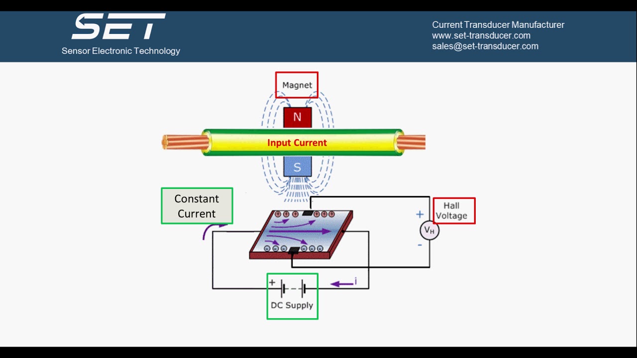
How Hall Effect Current Transducer Works - YouTube

Eddy Current Transducer-Sensor,Measurement,Working,Circuit Diagram

The block diagrams of the custom-built transducers: (a) voltage

Current Transducer: How does it work? What parts is it comprised of?

Pressure Transducer Wiring Diagram - Wiring Diagram