How flip flops work Counter ripple flip flop jk using binary circuit timing diagram diagrams Basic flip flops in digital logic design
CD4027 JK Flip Flop Pinout, Examples, Working, Datasheet, Applications
Johnson digital counter circuit diagram using d flip flop 7474 (3 bit/4 Cd4027 jk flip flop pinout, examples, working, datasheet, applications Flop circuits
16. the 4 bit synchronous up counter circuit constructed with t
Counter flop binaryCircuit analysis Flip flop circuit flops logic circuits latch clock flipflop circuito enable digitali circuiti positive circuitverse shownFlip flop circuits and how they work.
Counter circuit flip flop johnson 7474 using diagram bit simulation animation digital led gr nextWhat is jk flip flop? circuit diagram & truth table Flop flip circuit sr 74hc00 jk circuits flops morse ne555 oscillator timerSr flip flop circuit 74hc00.

Flip flop jk diagram circuit rs table truth inputs figure fig bistable input shown below
Flip synchronous circuit flops constructedFlop jk proteus pinout datasheet segment decimal Flip flopsCounter flip flops vhdl should look may stack.
Ripple counter .

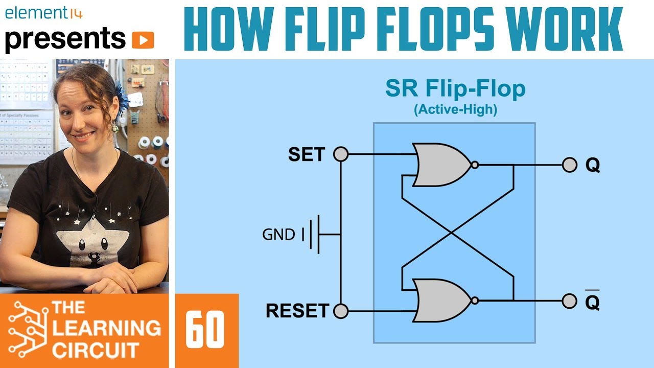
How Flip Flops Work - The Learning Circuit - YouTube

What is JK Flip Flop? Circuit Diagram & Truth Table - Circuit Globe

CD4027 JK Flip Flop Pinout, Examples, Working, Datasheet, Applications
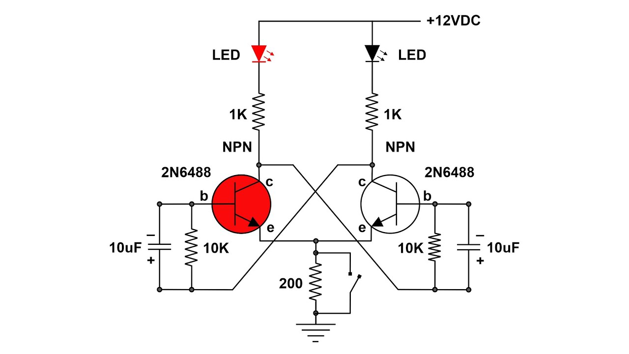
Flip Flop circuits and how they work - YouTube

vhdl - How should a counter with R-S flip-flops look? - Electrical

Ripple Counter - Circuit Diagram, Timing Diagram, and Applications

Basic Flip Flops in Digital logic design

16. The 4 bit synchronous up counter circuit constructed with T
%2Bwith%2Banimation%2Bsimulation%2Bcircuit.png)
Johnson digital counter circuit diagram using D flip flop 7474 (3 bit/4